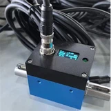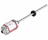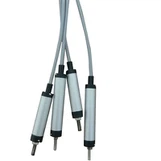


Gefran Replacement Linear Motion Position Sensor
The sensor is built for easy mounting by double
built in connectors, enable a large angle of misalignment and without back-lashes. A built-in connector system that is designed of reliability and safety contributes to excellent performance.These series can be used in a wide range of applications in mechanical and vehicle engineering industries as well as in automation and robotics technologies, combining remarkable robustness with high accuracy.


● Anodized aluminum housing
● Stroke lengths ranging from 50 to 900 mm
● Dual-rod drive mechanism (featuring dual spherical plain bearings)
● Outstanding linearity: ±0.05%
● Exceptional repeatability: ±0.01 mm
● Noise-free, smooth output via conductive plastic track
● Ultra-long service life:
> 100 × 10⁶ cycles
> 25 × 10⁶ meters
● Stroke Range: 50–900 mm
● Independent Linearity: ±0.05%
● High Resolution: Infinite
● Exceptional Repeatability: ±0.01 mm
● Max. Operating Speed: 5 m/s
● C193 4-pin connector
● Protection Class: IP65
● Operating Temperature: -30°C to 100°C
● Storage Temperature: -50°C to 120°C
New Features
● Gold-plated 43650/C193 connector (World exclusive)
● Gold-plated PCB (Sensor element) (World exclusive)
● Gold-plated pins (World exclusive)
● Optional shielded cable / multi-core shielded cable
Dimension :


Installation Steps:
- Secure the sensor body to the equipment bracket;
- Connect the universal ball joint at the front end of the pull rod to the moving component under measurement;
- Ensure that the direction of the pull rod's movement aligns perfectly with the direction of the object's movement;
- Lock the mounting screws in place after adjusting the zero point position;
- Connect the power supply and signal cables, then complete the calibration.

1. Ensure coaxiality.
2. Avoid overtravel.
3. When mounting horizontally, position the circuit board facing downward.
4. Avoid vibration and shock.
5. Ensure correct wiring.
6. Avoid electromagnetic interference.